
BUILD YOUR OWN PLASMA TABLE
BUILD YOUR OWN PLASMA TABLE
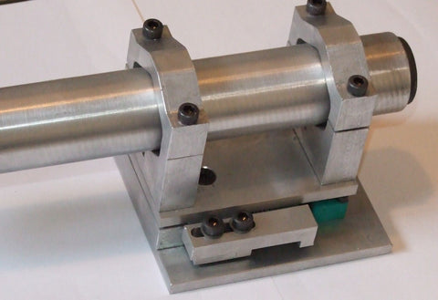
Floating Z axis ...(explained)
Sometimes we need to modify our CNC machine in order to achieve our machining goals as quickly and as efficiently as possible. CNC machines such as plasma, plotter cutters, lasers need mechanism that helps with measuring of material surface.
Good example of such modification is Floating Z axis.
The concept is pretty straight forward: Z axis has its own movable unit which is able to move when tool encounters with material surface.
Floating Z axis on a plasma machine is a safety feature that prevents any serious damage of your plasma torch, in case of hitting any obstacles on located on machine table.
For plotters and drag knife cutters, floating effect comes handy because it is much easier to apply pressure of the pen or knife onto material surface (paper, carton, vinyl etc) without the frustrating trial and error procedure.
Floating Z axis can also be used for measuring material top surface. In such case, floating z axis unit uses limit switch. When Z axis moves down towards the material, activated switch signals controller that surface of material was detected and zero work position of Z axis can be set.
SMALL GUIDE HOW TO USE OUR PRODUCTS:
FOR A HAND TORCH AND SMALL SIZE PLASMA TABLE WE RECOMMEND THIS LIFTER,IT HAS FLOATING SYSTEM ONLY:
.
FOR FLOATING AND BREAKAWAY SYSTEM WE RECOMMEND THIS LIFTER:

FOR COMMERCIAL USERS WE RECOMMEND THE HIGH END VERSION:

AND THIS:


YOU ALSO CAN ADD TO YOUR EXISTING LIFTER FLOATING OR FLOATING AND BREAKAWAY SYSTEMS.
HERE IS FLOATING ONLY SYSTEM:
HERE IS FLOATING AND BREAKAWAY SYSTEM:

WE MADE A DIVERSE VARIETY OF CHOICES TO ACCOMMODATE YOUR DESIGN.
LIMIT SWITCHES CONNECTION DIAGRAMS......

ALL PRODUCTS HAVE INCORPORATED SWITCHES FOR EASY INSTALL.

Plasma
Plasma cutting is a process that cuts through electrically conductive materials by means of an accelerated jet of hot plasma. Typical materials cut with a plasma torch include steel, Stainless steel, aluminum, brass and copper, although other conductive metals may be cut as well. Plasma cutting is often used in fabrication shops, automotive repair and restoration, industrial construction, and salvage and scrapping operations. Due to the high speed and precision cuts combined with low cost, plasma cutting sees widespread use from large-scale industrial CNC applications down to small hobbyist shops.
Process
Freehand cut of a thick steel plate
The basic plasma cutting process involves creating an electrical channel of superheated, electrically ionized gas i.e. plasma from the plasma cutter itself, through the work piece to be cut, thus forming a completed electric circuit back to the plasma cutter via a grounding clamp. This is accomplished by a compressed gas (oxygen, air, inert and others depending on material being cut) which is blown through a focused nozzle at high speed toward the work piece. An electrical arc is then formed within the gas, between an electrode near or integrated into the gas nozzle and the work piece itself. The electrical arc ionizes some of the gas, thereby creating an electrically conductive channel of plasma. As electricity from the cutter torch travels down this plasma it delivers sufficient heat to melt through the work piece. At the same time, much of the high velocity plasma and compressed gas blow the hot molten metal away, thereby separating i.e. cutting through the work piece.
Plasma cutting is an effective way of cutting thin and thick materials alike. Hand-held torches can usually cut up to 38 mm (1.5 in) thick steel plate, and stronger computer-controlled torches can cut steel up to 150 mm (6 in) thick.[1] Since plasma cutters produce a very hot and very localized "cone" to cut with, they are extremely useful for cutting sheet metal in curved or angled shapes.
History
Plasma cutting with a tilting head
Plasma cutting grew out of plasma welding in the 1960s, and emerged as a very productive way to cut sheet metal and plate in the 1980s.[2] It had the advantages over traditional "metal against metal" cutting of producing no metal chips, giving accurate cuts, and producing a cleaner edge than oxy-fuel cutting. Early plasma cutters were large, somewhat slow and expensive and, therefore, tended to be dedicated to repeating cutting patterns in a "mass production" mode.
As with other machine tools, CNC (computer numerical control) technology was applied to plasma cutting machines in the late 1980s into the 1990s, giving plasma cutting machines greater flexibility to cut diverse shapes "on demand" based on a set of instructions that were programmed into the machine's numerical control.[3] These CNC plasma cutting machines were, however, generally limited to cutting patterns and parts in flat sheets of steel, using only two axes of motion (referred to as X Y cutting).
Safety
Proper eye protection and face shields are needed to prevent eye damage called arc eye as well as damage from debris. It is recommended to use green lens shade #5. OSHA recommends a shade 8 for arc current less than 300 A, but notes that "These values apply where the actual arc is clearly seen. Experience has shown that lighter filters may be used when the arc is hidden by the workpiece."[4] Lincoln Electric, a manufacturer of plasma cutting equipment, says, "Typically a darkness shade of #7 to #9 is acceptable." Longevity Global, Inc., another manufacturer, offers this more specific table for Eye Protection for Plasma Arc Cutting at lower amperages :
Current Minimum Shade
(ANSI Z87.1+)
0-20 A #4
20A -40 A #5
40 A-60 A #6
60 A-80 A #8
Leather gloves, an apron and a jacket are also recommended to prevent burns from sparks and debris.
Starting methods
Plasma cutters use a number of methods to start the arc. In some units, the arc is created by putting the torch in contact with the work piece. Some cutters use a high voltage, high frequency circuit to start the arc. This method has a number of disadvantages, including risk of electrocution, difficulty of repair, spark gap maintenance, and the large amount of radio frequency emissions.[5] Plasma cutters working near sensitive electronics, such as CNC hardware or computers, start the pilot arc by other means. The nozzle and electrode are in contact. The nozzle is the cathode, and the electrode is the anode. When the plasma gas begins to flow, the nozzle is blown forward. A third, less common method is capacitive discharge into the primary circuit via a silicon controlled rectifier.
Inverter plasma cutters
Plasma cutting
Analog plasma cutters, typically requiring more than 2 kilowatts, use a heavy mains-frequency transformer. Inverter plasma cutters rectify the mains supply to DC, which is fed into a high-frequency transistor inverter between 10 kHz to about 200 kHz. Higher switching frequencies allow smaller transformer resulting in overall size and weight reduction.
The transistors used were initially MOSFETs, but are now increasingly using IGBTs. With paralleled MOSFETs, if one of the transistors activates prematurely it can lead to a cascading failure of one quarter of the inverter. A later invention, IGBTs, are not as subject to this failure mode. IGBTs can be generally found in high current machines where it is not possible to parallel sufficient MOSFET transistors.
The switch mode topology is referred to as a dual transistor off-line forward converter. Although lighter and more powerful, some inverter plasma cutters, especially those without power factor correction, cannot be run from a generator (that means manufacturer of the inverter unit forbids doing so; it is only valid for small, light portable generators). However newer models have internal circuitry that allow units without power factor correction to run on light power generators.
CNC cutting methods
Some plasma cutter manufacturers build CNC cutting tables, and some have the cutter built into the table. CNC tables allow a computer to control the torch head producing clean sharp cuts. Modern CNC plasma equipment is capable of multi-axis cutting of thick material, allowing opportunities for complex welding seams that are not possible otherwise. For thinner material, plasma cutting is being progressively replaced by laser cutting, due mainly to the laser cutter's superior hole-cutting abilities.
A specialized use of CNC Plasma Cutters has been in the HVAC industry. Software processes information on ductwork and creates flat patterns to be cut on the cutting table by the plasma torch. This technology has enormously increased productivity within the industry since its introduction in the early 1980s.
CNC Plasma Cutters are also used in many workshops to create decorative metalwork. For instance, commercial and residential signage, wall art, address signs, and outdoor garden art.

In recent years there has been even more development. Traditionally the machines' cutting tables were horizontal, but now vertical CNC plasma cutting machines are available, providing for a smaller footprint, increased flexibility, optimum safety and faster operation.
CNC Plasma Cutting Configurations
There are 3 main configurations of CNC Plasma Cutting, and they are largely differentiated by the forms of materials before processing, and the flexibility of the cutting head.
2 Dimensional / 2-Axis Plasma Cutting
This is the most common and conventional form of CNC Plasma Cutting. Producing flat profiles, where the cut edges are at 90 Degrees to the material surface. High powered cnc plasma cutting beds are configured in this way, able to cut profiles from metal plate up to 150mm thick.[1] up to thickness 30mm
3 Dimensional / 3+ Axis Plasma Cutting
Once again, a process for producing flat profiles from sheet or plate metal, however with the introduction of an additional axis of rotation, the cutting head of a CNC Plasma Cutting machine can tilt whilst being taken through a conventional 2 dimensional cutting path. The result of this is cut edges at an angle other than 90 Degrees to the material surface, for example 30-45 Degree angles. This angle is continuous throughout the thickness of the material. This is typically applied in situations where the profile being cut is to be used as part of a welded fabrication as the angled edge forms part of the weld preparation. When the weld preparation is applied during the cnc plasma cutting process, secondary operations such as grinding or machining can be avoided,[1] reducing cost. The angular cutting capability of 3 Dimensional plasma cutting can also be used to create countersunk holes and chamfer edges of profiled holes.
Tube & Section Plasma Cutting
Used in the processing of tube, pipe or any form of long section. The plasma cutting head usually remains stationary whilst the workpiece is fed through, and rotated around its longitudinal axis.[1] There are some configurations where, as with 3 Dimensional Plasma Cutting, the cutting head can tilt and rotate. This allows angled cuts to be made through the thickness of the tube or section, commonly taken advantage of in the fabrication of process pipework where cut pipe can be provided with a weld preparation in place of a straight edge.
New technology
Hand held plasma cutter
High performance cut
In the past decade plasma torch manufacturers have engineered new models with a smaller nozzle and a thinner plasma arc. This allows near-laser precision on plasma cut edges. Several manufacturers have combined precision CNC control with these torches to allow fabricators to produce parts that require little or no finishing.
Costs
Plasma torches were once quite expensive. For this reason they were usually only found in professional welding shops and very well-stocked private garages and shops. However, modern plasma torches are becoming cheaper, and now are within the price range of many hobbyists. Older units may be very heavy, but still portable, while some newer ones with inverter technology weigh only a little, yet equal or exceed the capacities of older ones. etc
MACH4 SET-UP
Changes in Mach4 vs Mach3:
In Mach3, Height Control was partially integrated into the Mach3 program, had no real error reporting when something went wrong, and used the same M3 macro as the spindle.
In Mach4, the we started from scratch to implement Height Control and everything is inside the ESS plugin (and TMC3in1 plugin as appropriate). This allowed us to have more flexibility, better error reporting and better performance overall. Another significant change is that instead of M3 we now use M62 to turn the torch on and instead of M5 we use M63 to turn the torch off. This has two distinct benefits. The first is that you won't accidentally turn on the Spindle in a machine that has a spindle and a plasma unit - a giant safety improvement. The second reason is that the M3 macro is not coordinated with your motion data and may be off by up to half a second! This is not a huge issue when you start a spindle and let it get up to speed for a few seconds, but when you are vaporizing metal, milliseconds count! With M62 and M63 the torch on and off commands are precisely synchronized with the start of the next motion command. This also allows for precise timing of a pierce delay.
Types of Height Control:
Manual Mode. This allows you to use the keyboard to adjust the Z height up and down, which is the simplest form of height control but it is 100% manual. This is common in Oxy-Acetlyne and water jet cutting. (Operationally this is almost identical to Up/Down Mode so the two modes are combined together. The only differences are two inputs and a button to select which mode you are in.) There are no anti dive capabilities here, other than the operator.
Up Down Pins Mode (like with Proma Controller), Manual Mode (Oxy-Acetylene) or no THC. This is the simplest kind of automated Height Control, and it offers the least flexibility. You have to manually adjust your target tip volts on the Proma controller, and the SmoothStepper just responds to UP and Down input signals to control the Z Height. (Operationally this is almost identical to Manual Mode so the two modes are combined together. The only differences are two inputs and a button to select which mode you are in.) There are almost no anti dive capabilities here. This will also let you run without THC (Torch Height Control) or in Manual mode if you are using Oxy-Acetylene.
Mach4's built in THC Mode (totally independent of the SmoothStepper). This utilizes a PLC to read the tip volts. Mach allows you to change your target tip voltage, and will generate Up and Down Z motion to correct the height. However, there is some lag and there are limited anti dive capabilities.
The TMC3in1 Torch Height Controller, which was designed to interface directly to the ESS and adjust the cut height over 1000 times per second. Since it communicates directly with the ESS and there is no buffering of data, there is almost no lag in response. There are 6 different Anti Dive modes, and almost all of the run time settings for the TMC3in1 can be controlled by macros in your GCode! This offers the most flexibility and performance.
WHAT DO I NEED TO GET STARTED?
Your going to need a few things to get started in the CNC Plasma Cutting business or Hobby. The basics are the same for someone that will be doing this as a hobby or as a full time business. I will go over the basics here and you can follow the links to get more specific info on each of the items.
There has never been more options as far as tables and equipment than there is now. When I started in 2000 there were only a handful of companies that built tables or components now there are thousands. Sorting through all of this can be a challenge and even overwhelming at times. I will help you sort through the options and find the best setup for your application.
Cost - Price varies from around 5K to over 200K and everywhere in between. Some of the factors that determine cost are the size of the machine which can be a super small 2x2 ft table to a 6x20ft table or larger. The most common sizes for hobby and light industrial tend to be: 4x4, 4x8 and 5x10 feet. Many people start out with a 4x4 table because it is usually the least expensive but quickly outgrow the table and want to make bigger things or more of something without having to load more material. Common steel sheet sizes are 4x8 feet and 5x10 feet. Which is why you see table sizes to match.
When I first got started I began with a 4x4 table then moved to a 4x8 table and now my latest table is a 5x10. I fully intended this to be a garage hobby but it quickly grew into a full time business. Trying to anticipate future needs and wants is critical and can save you a lot of money in the long run. I get a lot of people who ask me what size I should buy and I usually try and discourage them from a 2x2 or 4x4. More often than not they quickly outgrow these smaller tables. Going one size bigger than you think you will need is often a safe bet. Prices from a 4x4 to a 4x8 are usually not much different because the cost of the other components to run the machine remain the same.
The basic components of a CNC Plasma System:
The Cutting Table – This is where your material is going to go and be cut. Common variations are size ie. 2x2, 4x4, 4x8 and 5x10. Other variations are: Water tables which have water under the cutting surface which helps to eliminate smoke and dust as well as keep the parts cool and minimize warping. Downdraft tables use exhaust fans to pull the smoke and dust down and exhaust it outside of the work area, and then open tables which are the least expensive and have nothing below them but ground. We will discuss all of these and the pluses and minuses in the TABLE SECTION.
Plasma Cutter - This is the piece of equipment that is actually doing the cutting of the metal. It uses electricity to generate the plasma arc and cut through the metal. Plasma Cutters are most often classified by Amps. Common Amp ratings are 45, 65, 85, ect. There are quite a few companies that make plasma cutters but many are not specifically designed for mechanized cutting, they can usually be retrofitted and made to work. This is one piece of equipment that is critical to the quality of the cuts and the product you turn out. Skimping here often results in regret down the road. Check out the PLASMA CUTTER SECTION for more detailed information.
Software - There are a few software components that make up a plasma system. There is the design software where you make your part in a CAD (Computer Aided Drafting) program or your artwork in a program like Corel Draw, Adobe Illustrator or a host of other programs. Once your part has been created you export this file in a CAD format with the file extension .dxf. Once in this format you can open the file in a CAM (Computer Aided Manufacturing) program. This program is where you set up what material your cutting, where to start, what to cut and all of the cutting parameters. Once you have completed the CAM step you then export the file out in a file extension .tap. This is your G-Code (Machine Language) This code tells the machine where to go, how fast, how long how many amps to use and directs the operation of the torch and your table. There are a lot of choices in the world of software and I will cover them in depth in the SOFTWARE SECTION.
Compressed Air Source - Air not oxygen or any other special gas is the most common gas used in plasma cutting, IE “Air Plasma” machine. There are special industrial grade units that use, Oxygen, Argon, Nitrogen, and Hydrogen in the cutting process. On this site we will mainly be focusing on Air plasma cutting. Air Plasma units only need you to supply them two things to cut metal - Air and Electricity. Most plasma machines need a supply of around 100 PSI to make this all happen. Its critical to the quality of the cut that the air delivered to the plasma cutter be as clean and dry as possible. We will cover all of this in the AIR SUPPLY SYSTEMS SECTION.
Power - Power is one of the critical components that make all of this happen. You will need power to run the computer, control system and table drive system as well as power for the Plasma Cutter. Most tables only require 120v connections. Most plasma cutters on the other hand require a minimum of 240v Single Phase to power them. The larger the plasma cutter (more amps) equals more cutting capacity and requires more amps to make the larger cuts. Larger industrial and high definition plasma units will require 3 phase power. It is critical that you carefully evaluate the power requirements of the plasma cutter you are considering and look at the manufactures listed amp and circuit breaker requirements for the unit. Many small shops and garage based shops may not have the electrical wiring to support the larger plasma machines and may require expensive electrical upgrades. Make sure you evaluate the manufactures recommendation on the plasma unit you are considering and discuss this with a qualified electrician and evaluate your individual situation before making a purchase. What I believe to be two of the most widely used plasma cutters in the world in the Hobby and Light to Medium fabrication areas are the Hypertherm Powermax45 XP and the Powermax65. The 45 and 65 refer to the cutting amps of the units. We will discuss the plasma cutters in greater depth in the PLASMA CUTTERS SECTION.
Computer - Your going to need a computer for all of this two work and often two of them. Most software and machine manufactures will recommend that you have one dedicated computer to run the the machine and only have the software necessary to run the machine on it. You don't want to be surfing the Internet and playing games on the computer that is running the machine. Computers have so many things going on in the background and the more programs you add to the machine the more likely you are to have things running in the background. These background operations can disrupt and interfere with the cutting operation of your machine and ruin a project. There are plenty of people who risk it and do everything on one machine some are lucky and some are not. I have always kept my machine computer dedicated to machine operation. Its safer and a better option. The computer running the machine does not need to be a high end gaming PC. The machine requirements are pretty basic. Different Plasma cutting machines have different computer requirements. Most table manufactures will advise or supply the needed computer for the machine side of the operation. If building your own system from scratch you can often use a refurbished dell to make it work. Be sure to check with the table manufacture or control system manufacture before purchasing a computer so that you get one that works for your application. Many times manufactures do not recommend laptops for the machine computers due to several internal configuration settings seen in laptops. Your second computer will be the computer that you do all of your part or artwork design on and prepare your project for cutting on. This tends to be your higher end computer to handle the graphics and CAD operations. Once you have created your project on this computer you can export the finished G-Code over to your machine computer via, Wifi, Ethernet (Home or work Network) or a simple USB jump drive. I have my design software loaded on a laptop and my office computer to allow me to design anywhere I want or the comfort of my air conditioned office and then send the Job out to the machine to be cut. I will cover software more in depth in the SOFTWARE SECTION.
Control System - Your control system is best described as a box containing circuit boards and driver units that take the computer code that was created in the software and turn it into electrical signals that tell the Stepper Motors or Servo motors where to go when and how fast. Steppers and Servos are the motors that drive the Gantry and your torch around the table. There is quite a bit of debate over Stepper vs Servo and you can get more info in the PLASMA TABLES SECTION. This control system box and all of the internal components vary from manufacture to manufacture. There are control systems that are exclusive to Table manufactures and are sold with the table as a package and there are companies that make DIY packages allowing you to build your own table.
Turnkey System vs. Build your own or Kit system
This is another highly debated topic and one which has pluses and minuses on both sides. There are hundreds of turn key solutions offered today. A turn key option is one where you can purchase everything you need in one shot ready to cut. Everything is configured and ready to go all you do is supply air and power and your off and running. Advantages include faster, simpler, less of a learning curve, less to go wrong, no compatibility problems between components, one contact point if something does go wrong. The only real disadvantage is price. You are going to pay for all of this convenience with a higher price tag.
Kit or Build your own systems are almost always less expensive than turnkey but all the advantages of a turnkey system can now be disadvantages of a build your own or kits system. With a build your own system you have the ability to control the quality and components at every step of the project and you will be able to gain a great deal of knowledge about the inner workings of your system and likely fix problems on your own if they come up. Building your own will require skill and precision. Having a table that is not square or that has problems will affect your products quality and appearance.
My first two tables were build your own / Kits. I did a ton of research and learned a tremendous amount in the process. They were time consuming and at times frustrating but in the end they worked well and I saved a lot of money. For my third and current table I took all of the knowledge I had gained from the previous two and opted to do a turn key system. I knew all of the things I wanted in a table as far as features and components and found them in a quality and convenient for me package in my Westcott Plasma Pro Series 5x10 table.
What is Plasma - It is the the Fourth State of Matter
One common description of plasma is to describe it as the fourth state of matter. We normally think of the three states of matter as solid, liquid and gas. For a common element (water) these three states are ice, liquid water and steam. The difference between these states relates to their energy levels. When we add energy in the form of heat to ice, the ice melts and forms liquid water. When we add more energy, the water vaporizes into hydrogen and oxygen, in the form of steam. By adding more energy to steam these gases become ionized. This ionization process causes the gas to become electrically conductive. This electrically conductive, ionized gas is called plasma
How hot is the plasma arc? = The plasma is then forced through a fine-bore copper nozzle which constricts the arc and the plasma exits the orifice at high velocities (approaching the speed of sound) at a temperature approaching 28,000 °C (50,000 °F) or higher.. Compare this to the surface of the sun which is about 10,000 degrees F.
How Plasma Cuts Through Metal
The plasma cutting process, as used in the cutting of electrically conductive metals, utilizes this electrically conductive gas to transfer energy from an electrical power source through a plasma cutting torch to the material being cut.
The basic plasma arc cutting system consists of a power supply, an arc starting circuit and a torch. These system components provide the electrical energy, ionization capability and process control that is necessary to produce high quality, highly productive cuts on a variety of different materials.
The power supply is a constant current DC power source. The open circuit voltage is typically in the range of 240 to 400 VDC. The output current (amperage) of the power supply determines the speed and cut thickness capability of the system. The main function of the power supply is to provide the correct energy to maintain the plasma arc after ionization.
The arc starting circuit can be Blowback design which is used on the Powermax Series or a high frequency generator circuit that produces an AC voltage of 5,000 to 10,000 volts at approximately 2 megahertz. This voltage is used to create a high intensity arc inside the torch to ionize the gas, thereby producing the plasma.
The Torch serves as the holder for the consumable nozzle and electrode, and provides cooling (either gas or water) to these parts. The nozzle and electrode constrict and maintain the plasma jet.
Sequence of Operating a Plasma Cutter
The power source and arc starter circuit are connected to the torch via interconnecting leads and cables. These leads and cables supply the proper gas flow, electrical current flow and high frequency to the torch to start and maintain the process.
1. A start input signal is sent to the power supply. This simultaneously
activates the open circuit voltage and the gas flow to the torch
(see Figure 2). Open circuit voltage can be measured from the electrode
(-) to the nozzle (+). Notice that the nozzle is connected to positive in
the power supply through a resistor and a relay (pilot arc relay), while
the metal to be cut (work piece) is connected directly to positive. Gas
flows through the nozzle and exits out the orifice. There is no arc at this time as there is no current path for the DC voltage.
2. After the gas flow stabilizes, the high frequency circuit is activated.
The high frequency breaks down between the electrode and nozzle
inside the torch in such a way that the gas must pass through this arc
before exiting the nozzle. Energy transferred from the high frequency
arc to the gas causes the gas to become ionized, therefore electrically
conductive. This electrically conductive gas creates a current path
between the electrode and the nozzle, and a resulting plasma arc is formed. The flow of the gas forces this arc through the nozzle orifice, creating a pilot arc.
3. Assuming that the nozzle is within close proximity to the work piece,
the pilot arc will attach to the work piece, as the current path to positive
(at the power supply) is not restricted by a resistance as the positive
nozzle connection is. Current flow to the work piece is sensed
electronically at the power supply. As this current flow is sensed, the
high frequency is disabled and the pilot arc relay is opened. Gas ionization is maintained with energy from the main DC arc.
4. The temperature of the plasma arc melts the metal, pierces through
the work piece and the high velocity gas flow removes the molten material
from the bottom of the cut kerf. At this time, torch motion is initiated and
the cutting process begins.
Variations of the Plasma Cutting Process - Conventional Plasma Cutting
This process generally uses a single gas (usually air or nitrogen) that both cools and
produces the plasma. Most of these systems are rated at under 100 Amps, for
cutting materials under 5/8" thick. Primarily used in hand held applications
Dual Gas Plasma Cutting
This process utilizes two gases; one for the plasma and one as a shield gas.
The shield gas is used to shield the cut area from atmosphere, producing a
cleaner cut edge. This is probably the most popular variation, as many different
gas combinations can be used to produce the best possible cut quality on a given
material.
Water Shield Plasma Cutting
This is a variation of the dual gas process where water is substituted
for the shield gas. It produces improved nozzle and work piece cooling
along with better cut quality on stainless steel. This process is for
mechanized applications only.
Water Injection Plasma Cutting
This process uses a single gas for plasma and utilizes water either radially or swirl
injected directly into the arc to greatly improve arc constriction, therefore arc density
and temperatures increase. This process is used from 260 to 750 amps for high quality
cutting of many materials and thicknesses.This process is for mechanized applications only.
Precision Plasma Cutting
This process produces superior cut quality on thinner materials,
(less than 1/2") at slower speeds. This improved quality is a result of
using the latest technology to super constrict the arc, dramatically
increasing energy density. The slower speeds are required to allow the
motion device to contour more accurately. This process is for mechanized
applications only.
WHAT CAN I DO WITH A CNC PLASMA MACHINE
Well you can do just about anything you can imagine! Well within reason. You need to make sure what your cutting is electrically conductive ie - Steel, Aluminum, Stainless steel, Titanium, Copper ect. If its one of those you can cut it with the plasma machine.
In most cases you are going to be limited to 2D or flat cutting unless you have a high end machine with bevel capabilities or you have a rotational axis ie tube cutting accessory.
After those little details if you can draw it or have it drawn for you usually your only limited by your skills or abilities. There is a learning curve involved and getting to know your machines capabilities and how to use your software. When I say machine capabilities what I’m talking about is plasma cutting has limitation on how small you can cut. For example you are limited to the amount of detail you can fit in a space. Your not going to fit the 10 commandments in a 3x3 inch space. As you begin do design and experiment with your plasma machine and table you will learn the limitation of both.
What you cut can be broken up into two broad categories: Parts and Art.
Parts tend to be things that will be welded, bent, formed, drilled, tapped, or processed as part of an assembly or attachment to something else. Examples include: brackets, tabs, braces, engine components or suspension components etc.
Art is about everything else. It can be signs, pictures, abstract metal forms and host of other things that you want to call “ART” you can also combine these two categories to make things like benches, chairs or even a door for a jeep.
Below are some examples of items that we have created with our machine in the past.
This is a 14g steel painted multi layer flag that is 8ft wide and was done for a local police department. This was cut with a Hypertherm Powermax65
====================================================================================================================================================================================
Interesting Reading....
Choosing Your CNC Router
Why CNC?
A CNC router is just a tool – like a tablesaw or a drill. Because it is computer controlled, it lets you do things quickly and easily and with a degree of precision that isn’t realistic any other way. It can open new doors for your business and free you from subcontractors and their schedules. It will become a go-to tool for more and more jobs as you learn how to use it better.
Almost as important – designing things in the computer forces you to think differently about a process. It makes you better. I discovered this as a carpenter (boatbuilder) when I got my first CNC router and felt my focus shift from trying to make a shape, to deciding what shape to make. I have seen it evolve as I started to think about machining as planning and programming instead of carving – and again as I have learned about 3D printing, where execution is even more automatic. Each shift adds another layer of abstraction above manual work, and forces complete decisions earlier in the process. This is annoying at first but once it becomes just “the way” it makes everything easier. And it’s a good learning experience – you can’t micromanage a robot!
Why a Router?
Assuming you have a type of work you want to do that requires the machining of a relatively soft (foam to aluminum) material in sheets or 3D surfaces, a router is probably the right tool.
- If you are cutting only thin sheets of moderate-density material, a laser is worth a look.
- If you are machining precision parts from high density foam or metals, a machining center may be best.
- If you are cutting 2D profiles in metals, a plasma or water-jet may be better. Water-jets are pretty great for composite panel cutting!
A router is ideal for machining sheet goods – think production cabinet shop. This is what most of the CNC routers in the world do day-to-day. Most manufacturers sell into this market and have machines optimized for this purpose with high speeds, vacuum hold-down, drill banks and sheet loading systems. If your work is limited to 2D machining of sheet goods, you have fewer choices to make and plenty of options.
The composites industry does a lot of 3D shape-making. Most products are designed in software to a high level of detail, and most customers will assume that all but the simplest shapes will be built from machined geometry. Most of the routers I have seen in use in composites shops have been doing a mix of jobs. There’s some sheet cutting, some 3D surfacing and maybe part trimming. In larger operations, there will be more dedicated machinery and more job-specific optimization. This makes sense – you don’t want a million-dollar room-sized 5-axis cutting plywood sheets!
Do You Really Need One?
There are lots of CNC routers out there. Why do you want one? If you are a manufacturer trying to solve a specific set of production problems you will have an easier set of choices. If you are a job shop, you will have to think very hard about what “sweet spot” makes sense as you look at the costs involved and the corresponding opportunities for profit.
It is a good idea to write down a bunch of jobs that would be typical of 80% of the work you would be doing. It is probably smart to optimize for this and subcontract the remaining 20% out – or figure a way to do it sub-optimally in-house. If you are starting out and don’t have workflow or products yet, be very careful about committing to the wrong thing too soon. Try jobbing out the work initially – it will teach you a lot just by listening to the machinists talk about the work. If you work with vendors that have equipment similar to what you are considering for your own facility, you can learn a ton! A big spreadsheet with as much real information as possible is always a good idea, but at some point you’ll have to feel out the risk and make a “gut+data” decision.
Look at what it costs to have somebody else do the machining. Remember you are probably paying for material and labor, and that there is a lot of labor that is not specific to the machining process. Once you have a machine, you will have new commitments in terms of CAD and CAM work and material purchasing and handling. If you are having a large established shop do your work, they may have very nice equipment and it may actually be cheaper to have them produce for you if they have the capacity and can meet your schedules. Ask them what would make it easier for them – and then act on it!
It is my opinion that the best reason to buy CNC equipment is to control your future. If you can do something yourself, you control the schedule and the information. Customers will come into your factory and see a level of commitment to technology and capital investment and they will know you are serious. You won’t be waiting on (and blaming) subcontractors for your delays. Changes will be less impactful – and there are always changes! Modern machine shops are just very well organized rooms full of skilled workers and expensive computer-controlled machinery. If you want to be one of those, you will need to own a bunch of stuff and manage it masterfully. If you can get by with just hiring one that’s a great option – and why job-shops exist.
You won’t have a successful business by being a slightly cheaper “me too” business, but you can absolutely become a better provider of value for your customers if you can control your workflow more completely and provide confidence-inspiring certainty about when work will be complete.
What to Get:
You have lots of choices!
Big or small? New or used? How many axis? Tool changer? Vacuum hold-down? Control? Lease or cash or bank loan? Warranty? One nice machine or two crappy ones?
This picture shows the basic categories of machine used in the composites industry. I have owned all but the monster 5-axis, but I have always wanted one! They’re expensive.
Your choice will probably come down to money in some for or another. If you are doing this as a hobby then it is easier – you know how much you can spend and you want the best machine for that money. If you are a business, there is the chicken-and-egg money problem:
“If we have [machine X] we could get [job Y] and then we’d make [Z profit] !”
and:
“If we have payments of [$A] then we’ll have to take [job Y] just to keep [machine X].”
If you buy more machine, you will be able to do more with it – more of your own production or in the case of a job shop, a greater quantity and variety of work. Either way, unless you have a very good idea of what you need and the ROI, it is probably better to buy a simpler machine than you would ideally have, and then once you have learned a lot, buy either a second machine to share the load, or upgrade to a more focused and (hopefully) profitable option. Having expensive machine payments is stressful, and feeling like you have to stray from your core business just to “feed the beast” is not a good long term strategy. You can learn very quickly and having experience with a simple machine will inform your future choices – think about it as an investment in knowledge and a process rather than the purchase of a tool.
Now, you’re looking at machines… there are lots of decisions to consider and lots of parameters. Some things to think about:
Mechanical:
For all but the cheapest machines, you want to buy something with high quality mechanical components that can be readily maintained and replaced if needed. There will be choices regarding the types of linear bearings and axis-moving devices. Most well-established machine builders have reached a kind of “sweet spot” where the engineering choices deliver a mix of economy and performance that matches the needs of their average customer. A $15,000 Shopbot has gear rack and v-rollers running on steel rails – and it works well enough for the average Shopbot customer. A $350,000 CMS or CR Onsrud 5-axis has helical rack and pinion or precision ball-screws and huge ball-bearing linear guides – and this is the right choice for their typical customer. Your job is to decide what kind of customer you are!
An old Shop sabre with the linear rails and ballscrews and wrench-change spindle.
Most likely the machine you are after will have profiled linear rails on all the axes. These are almost universal in all but the cheapest machines – and they’re awesome. Linear rails are profiled so that streams of ball bearings can recirculate through the bearing and allow it to slide effortlessly along the rail. You will want to mind cleanliness and lubrication. For machines cutting a lot of composite materials, an auto-oiler will be helpful to keep the bearings purged with positive pressure lubrication. Buildup of dust on linear bearings can cause them to clog up and stop the balls from rolling. Sometimes the ends pop off and balls come out. If you are looking at a used machine, keep an eye on the general cleanliness and level of lubrication. If the machine is covered in clumps of grease/oil and dust then look around to see if all the bearings are intact and in good condition.
There’s a lot of discussion about ball-screws vs. rack and pinion for linear motion in CNC routers. Both options are great! Both also have areas where they can struggle. As usual, whoever designed your machine probably has lots of experience with this and made choices that combine to create a useful set of compromises. It is mostly an issue if you are buying a used machine.
Rack and pinion drives typically have a reduction gear so that the servo can run at a higher RPM where it has more torque. Typically reduction gears on industrial machines are around 5:1 on linear axes. These are usually durable and long-lasting, but can be expensive to replace. The biggest drawback of rack and pinion is the backlash that can happen if the gear pinion is not properly meshed with the rack. Most machines have adjustable plates holding the servo and gearbox that can be held firmly against the rack. These will often need to be adjusted on older machines of machines that have made a road journey.Servo (left) and ballscrew (right) connected by timing belt on a Motionmaster.Linear rail and large gear rack on an older CMS router.Linear rails and ball-screw with reduction pulley for timing belt on a Quintax.
Ball-screws are generally more accurate than rack and pinion drives, but not in a way you’d notice on a router. They are also limited in length, even in situations where the screw is held static and the ball-nut is rotated. Big machines (axes longer than 10′ or so) will almost always have rack and pinion drive systems. Your biggest concern with ball-screws is cleanliness and wear on the ball-nut. Ball-nuts have a recirculating line of ball bearings that ride in the groves of the screw. These ball bearings can get gummed up and stop rolling smoothly. In most cases machines are designed to allow removal of ball-screws (or at least decoupling of the ball-nut from the load so it can be slid into the open for cleaning. You will almost never need to replace an actual ball-screw unless something seriously traumatic happens – unless it is like 20 years old with 40,000 hours on it. Ball-nuts are easily replace and in some cases can be “tightened up” by replacing the balls with ever-so-slightly larger balls. On used machines – look out for escaped balls – a bad sign!
Motors and Motion:
Your machine will have electric motors that make it move back and forth (or around) each of it’s axes of motion. These choices can be complicated and it’s not always obvious what will be the right mix of economy and performance. Self-serving marketing talk from machine manufacturers doesn’t help!
Generally you’ll have two main options: “servos” or “steppers.” Steppers are simpler and cheaper – they run “open-loop” which means that the control sends signal to the motor but the motor never phones home to say if it actually did what it was asked to do. Servos are more complicated, more powerful and have “closed-loop” control – which means they are constantly going back and forth with their drives (and often the CNC control too) to make sure they are actually where they are supposed to be. Generally, steppers are found only on the least expensive machines – the well under $20,000 range. Servos and “hybrid-steppers” which are steppers with a “feedback loop” like a servo are more and more common and inexpensive – and are found on ever-cheaper machines.
Gantry on an older Larken router showing stepper, gear rack and round profile rails.
So a little more about steppers – because they aren’t a bad option for the right machine. I once had a Shopsabre router with steppers and it never went more than 300 inches per minute but it was a wonderful machine for making 3D molds – especially for the $7 grand or so I paid for it used. It just went and went – all day long – and the cut quality was great. As long as you don’t over-ask with steppers, they are very reliable and can provide tremendous value. Steppers are controlled by “step and direction” signals. These are electrical pulses that tell the stepper drive (small computer that controls the stepper) to go forward or back by one step. The value of a step is defined in the control software – so a step could be 0.01mm for example. The control sends pulses to the stepper drive telling it to go forward or back one step – and it does it over and over – thousands of times a second.
The problem with steppers is that if you do over-ask, either in speed or acceleration, they will “lose steps” – that is they will not actually move when commanded by the control. When this happens, steppers never speak up because the control is open-loop (no feedback from motor to drive) so the machine goes merrily on it’s way chewing up your part or stabbing its table until you run over frantically and crush the E-stop. But if you’re looking at a low cost machine, don’t discount steppers as an option. They won’t be the fastest and every now and then lost-steps could be a problem – but it will almost always be your fault for programming too aggressively or fixturing the work wrong.
Servos are the standard for industrial CNC machines and have been for 25+ years. Servos are motors that have an “encoder” attached to the shaft inside the motor casing. The encoder is a device that creates an electrical signal that keeps track of the position of the motor shaft. Some encoders are “incremental” and some fancier ones are “absolute”. Incremental encoders output the position of the shaft relative to a zero-position – like 12-o’clock on a clock face. Absolute ones tell the position of the shaft – and number of rotations – from a starting position even if the motor is turned on and off. Absolute encoders don’t require homing the machine every time you turn it on – the servos just “remember” where they are. It’s great until you have a problem – then it’s just more complicated. I have owned one machine with absolute encoders and it worked beautifully. On high-end machines, absolute encoders offer better performance and repeat-ability and are pretty much standard.
Servos are controlled by “servo drives” which are simple computers (usually on a card or in a small enclosure) that control the power to the motor and read the “feedback” from the encoder. The motor is never exactly where it is commanded to be and the servo drive increases or decreases the electricity to the motor to keep it in the right place. If it gets behind, the drive gives it a little more power. If it gets ahead, it reduces power it and monitors the encoder to get it back to the commanded position. Imagine a trained bear walking on top of a rolling barrel – it balances up there by constantly walking forward or back. Like the bear, servo drives are always monitoring and tweaking their situation. If you push on a light duty machine with servos, you can feel it push back. If you push too hard and it can’t fight you, it will “fault” – or give up and throw an error to the control that says “uncle” and it will stop running its program and require some type of reset. In practice this adds a margin of safety and keeps the machine from damaging itself (that much) in the event of a crash.
Gantry drive servo on CMS 5-axis router.
Almost all newer machines will have what are called “AC servos” (or sometimes “brush-less DC servos”). These are motors with a permanent magnet rotor (spinny bit) and coils in the stator (static thing that surrounds the spinning bit) that create a rotating magnetic field. AC servos don’t have brushes. AC motors are very responsive and can hold position very well within a tight band. Because the servo drive has lots of control over the motor, AC servos typically operate with a very small “following error” – which is the amount that the motor is not quite where it’s supposed to be. CNC controls deal with following error differently, and usually industrial controls manage it in the control itself. AC servos are usually controlled with either an analog signal (usually 0-10vdc) or a digital protocol. Tuning AC servos is typically done by plugging them into a computer or by adjusting parameters on a screen. Many drives offer “auto-tune” functions.
Some lower cost servo systems are commanded with “step and direction” signals like a stepper. These operate like steppers from the control’s point of view – just much more powerful steppers that return a fault when they are overpowered. Many PC based controls (see below) do not offer the option for servos to return position feedback to the control, so servo faults will stop the machine, but the moving position will not be as tightly controlled as with a fully integrated system. This is fine for lighter duty machines where they don’t have to accelerate heavy chunks of metal. It is a good idea to know how servos are controlled on a machine that you are considering. Lots of the lower-end servo powered machines run these simpler servo systems – and properly engineered and integrated they offer a nice middle-ground between industrial controls and their complexity and steppers and their drawbacks.
Older machines may have DC servos. These motors have a permanent magnet stator and coils in the rotor – so they have to have brushes. Theoretically they have more rotor inertia and less optimal heat dissipation which reduces their performance but when properly specified they work fine. Brushes do occasionally need replacement but this is a once-every-few-years problem. If you are looking at a used 1980’s to early-2000’s machine you will likely be dealing with DC servos. One thing to be aware of is that servo tuning is important – and that your control needs to have each axis set with the same “following error” for the same RPM. This can be a little bit of a black art, but there are many sources of information on how to do it. DC servos are controlled with much more following error than AC servos, and so they need to be “tuned” so that the axis is where the control thinks it is! DC servos are typically tuned with several small pots on the servo drive.
Stepper, DC Servo, AC Servo.
One other stepper vs. servo consideration is machine homing. Most machines will home to a limit switch (unless they have absolute servos) and that will tell them when they have reached the “home” or “zero” position. One cool thing about servos with encoders is that they will home to the limit switch for a rough location and then will home to what is called the “reference pulse” on the encoder – say the 12 o’clock position. This is a very accurate home position that will repeat to a very small tolerance band compared to homing to a switch alone. So with servos, you’ll typically have a home position that is accurate to less than 0.001″ (.04mm) – which is nice for fixturing tight tolerance work.
Controls:
CNC controls are the computers that tells each axis of motion and each cutting tool to move with coordinated motion following the “orders” written by the CAM software. The task is divided into these main activities:
- decoding the g-code or part program and turning it into motion commands
- timing the motion commands so that they result in the right combination of synchronized acceleration, velocity, and position changes for axes and cutting tools.
- sending the motion commands to the axis motors and spindle
- receiving feedback from the axis motors and correcting errors
- continually checking machine status (air pressure, servo monitoring) and safety (e-stop, pressure mats, etc.)
There are two main categories of controls: “industrial” or “PC-based.” Industrial controls are purpose built to drive automated machinery. They are one-trick-ponies and usually have limited interfaces and options, but are ideally suited to running machinery. They can be very expensive, often tens of thousands of dollars for a control system. PC controls are just a standard computer with software that issues commands to machine control hardware.
A PC-based control has a standard PC as the user interface – usually Windows or Linux. It uses the PC’s peripheral interfaces (USB, Ethernet, PCI, etc.) to send commands either directly to a breakout board or more commonly to another piece of hardware that handles timing and interface with stepper or servo drives. The advantages usually start with price, as PC controls are less expensive in most cases. It is also usually easier to interface with a PC control if you are not used to operating CNC machinery. There’s lots of storage and a mouse and files in folders – just like home!
Industrial controls are a different animal. Inside there is still a computer – but also a lot of specialized hardware to allow connection to servos and lots of input and output connections for machine sensors and features. Usually these controls have CNC-specific buttons and switches – feed and spindle overrides and buttons for specific functions. Sometimes it’s hard to get your head around at first! Industrial controls are generally found on more expensive machines, and are typically designed to operate for decades without drama – and sometimes they actually do! They are very robust and operate with a much simpler operating system so there’s no typical PC BS – no Windows update deciding to restart at a bad time!
One very important consideration for PC and industrial controls is “block processing time” – the time that it takes the machine to read and command a block of g-code. For large complicated 3D surfaces, the machine will have to do lots of thinking to keep up with all those line segments and arcs. You want as fast a control as you can get. This is especially likely to be an issue with older machines – old computers are slower and modern CAM packages aren’t shy about outputting huge quantities of code.
Another consideration is “look ahead” or trajectory planning. This is a feature in most all CNC controls that reads the code ahead of the current line and attempts to optimize machine acceleration for the coming path. A machine with many lines of “look ahead” will see a corner coming and slow the machine ahead of time rather that banging into the corner and risking chatter or servo-overshoot. The best machine controls will have highly adjustable look-ahead parameters allowing you to specify the accelerations and the allowable deviation from the programmed path to enable smooth machine motion.
It is hard to say what you should choose – typically a machine will come with a control that is aligned with the price point and level of performance. I would choose an industrial control for a larger machine because it is safer and generally more able to provide a complete operating experience. Things like feed and spindle override knobs (instead of sliders on a screen) and real buttons for cycle start and feed-hold are easier to use and give better intuitive connection with the machine. File handling on older industrial controls can be a hassle – drip feeding with DNC when there’s not enough onboard storage for a large program – but once you’ve sorted it out it isn’t a big deal.
It is good to try to find a control that uses a relatively standard kind of g-code. This will be nice as you or your operators and programmers get used to looking at code and modifying it – and will make it easier to deal with post-processors. You might not hand write any g-code (why would you?) but you’ll become good at looking at it and knowing what going on roughly and sorting out any problems. Standard g-code is easy to read and the internet is full of discussions about all manner of problems. I guess this is an example of the “don’t get/do anything too weird unless you like adventure” model!
Spindles:
The spindle is the “teeth” of the machine. Your spindle could be anything from a 1hp trim router to a high precision tool changing water cooled 25hp monster that costs as much as a nice car. Something in the middle is probably going to be good.
Unless you have a very small machine, a standard wood router is going to be disappointing. Yes, the price can’t be beat – but they are noisy and weak and probably not a good choice for commercial work. Some options like Kress high speed die grinders work well and there are a growing number of low power spindles that work with hobby -scale machines like Shapeoko, X-Carve, Stepcraft and others.
Electrospindles are precision high-speed electric motors that combined with heavy-duty bearings and some tool clamping mechanism, allow for lots of spinning under a variety of load conditions. The big price jump happens when you go from a wrench (manual, with wrenches) tool change to auto tool change (ATC). With an automatic tool changer, your machine can run a program unattended that uses a bunch of different tools. This is awesome! The added benefit is that the length of each tool is consistent from tool change to tool change. With a manual tool change spindle, you have to re-measure tools every time you change them unless you have a clever system – and clever systems are easy to mess up!
Wrench or manual tool change spindles cost from $1000-$5000 roughly. They are usually very robust and can run forever with very little maintenance. Typically there is a threaded collet and nut assembly that allows you to clamp a tool in the spindle. Most wood router spindles use ER collets. To change the tool, you use two wrenches and open the collet nut, remove the collet if you need to change to a different size, snap the new collet in and loosely screw it onto the spindle. Then you put the new tool gently into the collet and tighten manually until it won’t fall out – then you use the two wrenches again to snug it up tight. You’ll have to re-measure the new tool and run the program. It works great, but after the 20th time in 3 hours you’re going to wish you had an auto tool changer!
Auto tool change (ATC) spindles use a “taper” and a draw-bar mechanism which grabs a feature in a toolholder and pulls it tightly into line with the spindles shaft. The two main types you’ll find in wood routers are ISO-30 and HSK-63 (usually with an F). HSK spindle tapers are a little higher-end and offer some benefits. I can’t quantify the benefits, but have had both kinds and HSK seems like a more “positive” grip – but not so as you’d notice in day to day use. Some really beefy machines (Haas GR series routers for example) use CAT-40 spindles which are bigger and more metal-oriented.
ATC spindles require tool-holders for each tool. These are precision adapters that clamp the tool on one end and interface with the spindle nose on the other. They cost from $50 (cheap or used) to $400+ each. Tool-holders will have a system for clamping the tool, often an ER collet or a heat-shrink or hydraulic clamping system. ER collets are fine for most anything wood or foam related and there is a whole world of high end tool holding stuff if you need to go there.
Motion master tool changerAXYZ spindle with pneumatic dust hoodDMS tool changer
A machine with an ATC will have some type of tool rack or carousel for storing all the tools in their tool-holders. It is programmed to find a certain tool number in a given spot. When your code asks for a new tool, it will go drop off the current one and grab the new one. Your tools will be different lengths from the nose of the spindle, so you will have to tell your control (often this is partially automated) how long each tool is relative to a reference. This makes it possible to use many tools in any given program, and also to change out tools or adjust the amount a tool sticks out of its holder and not re-post the code from the CAM software. This is especially useful with a 5-axis machine and is one reason to avoid machines with a “double-ended spindle” or without a tool-changer if you plan on using multiple tools per part. A double ended spindle has only two tools at a time, and they are changed with a wrench – so the tools need to be remeasured and the program re-posted each time the physical distance from the tool tip to the point where the rotary axes intersect of the rotary axis – called the “pivot length.” Double-ended spindles really shine for part trimming in a production environment where two tools are plenty and the time to switch tools is just seconds.
Spindles need to be cooled because all that spinning makes a lot of heat! The most common method is a fan – either shaft mounded or electric – that blows air through the spindle housing. Other options are compressed air and water. Water cooled spindles tend to be either very cheap or very expensive. I would suggest you avoid the cheap ones. A fan cooled spindle is fine for almost all situations. Very high-end machines will use liquid cooled spindles to control thermal expansion and because they are more compact than externally mounted fans.
Fixturing:
You’re going to have to hold down the things you will be cutting. This is called “fixturing” and is a major component of the art of machining. There are a bunch of different methods commonly used but the basic goal is always the same – don’t let the workpiece move, and don’t spend any more effort to do this than necessary!
The simplest option is often to use screws or clamps to hold material down. For extended 3D machining of blocks of material, strap clamps like you’d use on a Bridgeport mill are awesome – just don’t hit them! Many machines come with an aluminum t-slot table (Techno, AXYZ, etc) which can do vacuum or t-slot hold down. Other machines come with threaded inserts fit to the table in a grid. My first few machines had two sheets of MDF fastened to the frame of the machine, and I just held stuff down with square-drive screws – only hit a few dozen! The key here was to fasten the first sheet with countersunk bolts and then glue the second sheet on top so it was fastener-free and could be machined down to a flat surface.
For sheet-goods, the industry standard method of fixturing is vacuum hold-down. This is when a large (or huge!) vacuum pump sucks the workpiece down to the table and holds it there with vacuum. Vacuum fixturing is often a factory option on mid to high-end machines. If you are cutting sheets of material, chances are vacuum hold-down with be the best option. Pod and rail machines use vacuum to hold smaller pieces so the edges are available for machining and hole drilling. This is a great setup for small parts and can be added in modular fashion to machines that have just a flat table. Vacuum is expensive though – running a huge vacuum pump – and if things go wrong it is easy to have a part shift on the table – resulting in junk!
My rule of thumb is that if a cutting job is going to take longer than an hour, you should fixture it with clamps or fasteners – but that’s just me.
For fixturing parts for (3 or 5-axis) trimming, a shaped vacuum fixture is often a great choice. Fixtures can be machined to match the surface geometry of the part and then fit with slits to hold gasketing material clear of areas that will be cut. A vacuum fixture should have some positive reference features to make sure the part is properly aligned before vacuum is applied!
There is an infinite variety of ingenious work-holding options but most setups will be pretty standard. Find a process (or a few) that is fast and accurate and work on streamlining it. Mastery of the process you choose is often more important than the choosing!
About 5-Axis:
5-axis machines are the most awesome and badass of all the CNC’s! With a 5-axis, you can reach almost all-the-way around parts. You can swarf-mill chamfers. You can drill holes on funny angles. You can trim complicated parts in vacuum fixtures. You can machine huge blocks of material into crazy shapes with undercuts. You can spend $20,000+ on a seat of CAM software… wait – that’s not fun.
The composites industry is a place where 5-axis CNC routers really shine. From mold making to trimming and machining finished parts, there is so much potential to make more accurate parts faster. Most high-end composites facilities do 5-axis machining. Many have for 20 years. It’s not new and there’s nothing novel about it, but it can still be a big step with a big learning curve. If you have the work to use the technology, and have an open mind about learning new processing techniques, then my advice is to not wait. A 5-axis can also do everything that a 3-axis machine can do. The benefits are huge and the cost of entry need not be too high!
First a note on CAM software. Traditionally it has been crazy-expensive to get CAM software that does 5-axis well. It kind of still is. Packages like Mastercam, Powermill, SurfCAM and Seimens NX are very common in shops or factories using 5-axis day-to-day. Cheaper options are available but are less powerful – I have used Madcam for 5-axis work for 7 years and it is a good sub-$10,000 option. RhinoCAM also has 5-axis support. Relatively recently, Autodesk (which also owns Powermill) has released 5-axis features in Fusion360, which is about $500 per year. There is a CAM extension product that offers significant 5-axis capability for an additional $1000/year or so. This is a pretty big development, and will make the barrier to entry for 5-axis programming even lower. Still, for programming a high end 5-axis you should buy good software. You should also consider a simulator (Vericut, Camplete, NCSIMUL, etc.) to test-run your code because a hard crash at that level can easily cost as much as a new car to fix. Buy the software, save the machine, get the up-time for free!
You can buy used 5-axis machines for $25,000. Usually a machine in this price range will be from the 1990’s and will have a 20-25 year old control. This can be either a wonderful chance to get your feet wet with 5-axis or a giant pain in the ass. I would only recommend this option if you are super tight on cash and have some decent machine-repair and old computer (and Ebay) skills. I’ve been there. While I don’t regret it, I was in a position where it was the only machine I could afford and I didn’t have the work to justify anything more expensive. Fundamentally, the basic components of a 20 year old machine are very similar to those of a new machine. Ball-screws and linear rails haven’t changed much. What has changed are the electrical bits (servos, control, etc.) and the mechanical methods of orienting the 4th and 5th axes. These changes are pretty significant!
New 5-axis machines can be had from about $150,000 (US) and up. Several manufacturers (DMS, Thermwood) make machines at an “entry level” price point that are designed mostly for trimming fiberglass and thermoformed plastic parts. Trimming machines are often open-configuration with a moving table and a fixed bridge. Sometimes two separate tables are used so an operator can be loading and unloading one while the other is being cut. One very common feature of trimming machines is the double-ended spindle. This is great for trimming, where you only need one (maybe two) cutters, and the tool change time is just a few seconds. For machining molds, or doing general purpose cutting, a double ended spindle is no fun. My advice is to look for a machine with a tool changer even if you think you’ll just be using it for trimming. Unless you’re running a huge plant where machines are very dedicated (and then why are you listening to me?) the flexibility of a library of tools will be very valuable.
As price goes up, machines can be had with enclosures and larger work volumes. For composites trimming, where there is lots of nasty dust, this is very nice. It may also be required by law for safety reasons if you live in Europe. These machines are the most common in larger composite shops where they are used for a mix of tooling and part trimming. Brands like Anderson, CMS, CR Onsrud, DMS, Thermwood, and Quintax all make medium range ($200,000-400,000 US) machines with large enclosed work envelopes, excellent controls and very high performance. Some machines are available with a continuous C-axis (the one that rotates around the Z-axis) – which is very handy for programming. Standard 5-axis heads can often turn up to one revolution in each direction, but it’s usually more like 180 degrees. This means that you will have to program retracts and unwinds often while working around a part. These are really easy times to crash your machine, and take up valuable cycle time. There is added complexity with a continuous C-axis, but it is really handy!
If the new machines are out of your price range (or payment level of comfort) you can find decent used machines from the 2000’s-2010’s for under $120,000 (US). The features you should look for are a modern control that is currently supported, and a stiff and easily adjustable head configuration. Controls from this era should have powerful look-ahead for path control, some type of TCP/RTCP control (see below), which will make programming much easier and will have hard drives, USB and Ethernet ports for easy file transfer. A 5-axis will always be more maintenance and setup headache than a similar sized 3-axis, but it will open up doors in pattern and mold making, and will allow you to deliver higher quality parts.
A note on control features: When programming a 5-axis machine, your CAM software will need to know the length of the distance between the tip of the tool and the center of rotation of the A or B axis. This is called the “pivot length” and will allow the software to calculate the position of the axes so the tip of the tool is in the right place. Many controls offer a feature called “tool center point compensation” or RTCP, TCPM, TRAORI, etc depending on the manufacturer of your control. This allows the machine control to “backtrack” from a tool tip point and orientation vector to calculate the correct position of the axes to position the tool in such an orientation. The pivot length (gauge length + tool length) is calculated in real time in the control so that you can run a program without knowing the exact tool length in the CAM system. Without this, you have to re-post your code every time you change the length of a tool. It also causes problems with tool holder styles and needed space for “unwind” moves. With RTCP enabled (usually though a G-code like you’d use to enable look-ahead) you can rotate the C-axis or B-axis and the tool tip stays in the same spot. The rest of the machine axes move to compensate for the changing tool vector. If you can get this on your machine, make sure you do, and make sure the control is fast enough to handle it.
Power:
If you are looking at an industrial machine it will probably require three-phase power. If you have this then all you’ll need to do it make sure the service voltage matches the machine requirements. No? You can get a transformer that will take one voltage and increase or decrease it to what you need. No problem! So 208v “stepped up” to 480v or 600v “dropped down” 380v. These usually cost less than $1000 for a used one – ask your electrician if they have one laying around. Keep in mind that higher voltages require smaller wire size for the same power. If you have along run to make, place the transformer at the right end of the long wires so that the higher voltage will travel on smaller (cheaper!) wire.
To use a 3-phase machine on single phase power you will need a phase converter. These come in different types, but you will want a rotary “CNC-rated” one and you’ll want to make sure it is sized correctly for the load. Expect to pay a few thousand dollars for a small one – and more for a bigger one. It can be a good option because industrial machinery is often cheaper used that “hobbyist” type machines so the cost of the phase converter will be offset – and you’ll have a beefier machine! Make sure your overall electric service is big enough to power the converter and all the other stuff you need. Generally the amp rating of a CNC machine will be “worst-case” with all the motors fully loaded up. This never really happens but you should plan your power budgeting as if it will.
Vacuum pumps are often the biggest power-consumers in a CNC router setup. These can often be wired for multiple voltages (might not need a transformer) so consider putting them on a separate circuit than the machine – as long as the CNC control is not to thoroughly integrated with the pump starter.
Also, please be careful! Big power is seriously dangerous and you can get dead very easily if you make a mistake. Hire an electrician!
New vs. Used:
The only things you get when you buy a new machine are the knowledge that nobody before you screwed it up and that you have somebody to call when it stops working right. These are valuable considerations! Even if you are an electrical wizard and gifted computer whisperer, these machines can be complicated and it is often not obvious what is messed up. Parts are hard to come by and down-time is expensive.
But used machines can be so cheap! This is what has always got me into used machines – the promise of a lot of bang for the buck. For the most part it has been a good strategy. I have also had broken machines sit for years because I was too busy to fix them – and this isn’t so good. It comes down to knowing yourself and your tolerance for risk – and your ability to sort out what is broken and fix it.
Generally the calculus comes down to the value the machine will provide vs. it’s cost, and the relative cost of down-time. If you are supporting a factory assembly process where a down machine stops production then by all means get a new one. If you are finally starting your own business but spent years running and fixing the boss’s CNC machinery and can take on maintenance and repairs – your cash will go way further on a used machine. The internet is a vast source of information and collective experience – so many times somebody else has been where you are and (bless ‘em!) wrote about it online. It won’t always be a walk in the park but given how much money you will save compared to a new machine, there is a compelling argument for taking the chance!
Keep in mind that machines have gotten consistently better over time. Controls are faster and more reliable and servo systems are more powerful and accurate. A new mid-range machine will have the same specs as a decade-old high-end machine, but it probably won’t be as heavy. You may find that all told you can get just as much value from a new cheaper machine and avoid the risks of buying used.
Old Machines:
I am more of a proponent of the used machine route than perhaps I should be – but there are some good reasons. In situations where cash is tight and the machine isn’t the core of a business – or where a used machine is the only affordable option I think it is better to just get something and use it. Say you want a 5-axis machine to trim your parts, but the cheapest new one is $150k – that’s a lot! You can find a 15-20 year old 5-axis for 1/4 that much. The metal parts are pretty much the same and it works. One of my most productive machines was a 1998 5-Axis Motionmaster that was 15 years old when I bought it. It was old but did tons of work I could never have done without 3’ of z-travel, and rarely needed repairs. The only down side is that the computer bits are so old that your CRT (what’s that?) could go any day and those control cards are getting rare. You may get a few more years out of it, but someday you’ll have to retrofit the control. It may just be better to get the machine, use it, make money with it and learn than to wait until you can afford the fancy new one.
See Appendix A: Where to look for used CNC routers at the end of this article!
Old machines are sometimes (often?) a little worn out. When you are looking over a machine, be sure to check it for sloppy-ness in the movement and see what is causing it. Most of the time there are ways to adjust the slop out of an axis once you measure it. With the machine on and the servos or steppers enabled, grab onto the various moving parts (but not the running spindle!) and push on it. It may move a little. It is a great idea to get a dial indicator and set it up so you can quantify the movement you feel in each axis. Most often this movement is fixable. What you want to look out for are situations where you push things back and forth and feel a clunk-clunk at each end and some measurable play. Here are some things that might be wrong:
- Gear pinion may not be seated all the way into gear rack. Most machines allow this to be adjusted so see if it is just loose. Worst case, gears can be replaced.
- The bearings at each end of a ball-screw often apply some tension to the screw, and this can be adjusted. If the screw itself is sliding back and forth as you apply pressure, this may be an issue. This can usually be fixed by tightening things up with some wrenches – or adjusted some other relatively simple way.
- Ball-nuts (that move along the ball-screw) can wear out, bind up or lose their balls. If the screw stays fixed but the ball-nut bumps back and forth this may be a problem. Ball-nuts can be replaced or repacked with slightly larger balls.
- Attachment of axis drive motors to the pinions or balls-crew is often through a gearbox or belt. Key-way and setscrews in these can be a source of slop, as can worn or loose belts themselves.
Parts availability is a big concern for older machines. Some manufacturers used common off the shelf parts – and this is great. Others made their own or mixed and matched and this can be a real challenge if things break. Ebay can be a great resource as long as you can be sure that your are buying the exact same component that is in your machine. There are a number of variants of common servos and drives and a single letter or number on the tag can be the difference between success and expensive smoke.
It is never reasonable to assume that just because a manufacturer is still in business, that they will support an older machine or have parts. Several common brands(Multicam, AXYZ, probably others…) have machines that aren’t that old for which the main control cards are no longer available. The rest of the machine may be fine but if that manufacturer-specific board goes, you’re looking at $20-30k to retrofit to a new supported control. This is fair enough – machine manufacturers can’t support things if they can’t get parts from their suppliers, but it is worth a call to the manufacturer to see what the real deal is on parts and support before you negotiate a price. Some manufacturers will help you out for free even if you aren’t the original owner and others will want you to pay for a support program before you can even get a technician on the phone. Just make sure you know what you’re signing up for!
Program transfer from new PCs to old CNC controls is a common problem when using old machines. Usually this is done with DNC (Direct Numerical Control) software over RS-232 – which is a standard for serial communications. In 1996, PCs came with serial ports – and your dial up modem might have had 56,000 baud rate for data transfer. Now its actually hard to get a computer with a serial port and DNC software sometimes requires DOS or some older version of Windows. The problem is compounded by the fact that big programs use a lot of memory, and older CNC controls didn’t have much. You can’t fit too much g-code in 128k of memory! The solution is to “drip feed” programs over the DNC link instead of fully uploading them into the controls memory. This is great once you get it sorted but it leaves things open to problems because the computer has to keep streaming data over the RS232 line as long as the program is running. Its a bummer if you’re 4 hours into a big 3D surface and the DNC stops dripping!
Back up your parameters!
If you are going to buy a used machine it is also REALLY important to copy the control parameters to a backup before the machine is disconnected from power. Parameters are the long list of numbers that tell a generic CNC control (Fanuc, OSAI, Fagor, etc…) how to interface with the specific machine configuration. This includes useful stuff like how many axes there are and how much a servo has to turn to make the X-axis move 1mm – and how to find tool #6, and how to open the spindle tool clamp. This is important stuff and your machine will be a total brick if those numbers get lost. Most controls can backup their parameters over DNC, Ethernet or USB. Don’t risk it – machinist forums are full of people begging for parameter backups to some obscure machine and too often this sends an otherwise usable machine to the scrap yard.
Another thing to be sure you back up are the compensation tables. Most medium to high-end machines will have been laser-measured when new and error compensation tables entered in the parameters. On a router, these can sometimes be in the .02″ range – sometimes more. You need these! It is possible to get a metrology company to come in and scan each axis of your machine and re-compensate it, but it will cost you several thousand dollars!
Repairs and Retrofits:
If (and when) you do have a major breakdown with an old machine, there are plenty of good repair and retrofit options. Even if the original maker of your machine is no longer in business (like Fadal, Motionmaster, etc…) you’ll usually still be fine because many of the people who were specialists are still selling that experience – somewhere else. Many independent repair technicians are available and if your machine is common there will be parts and knowledge readily available. Retrofit controls like Centroid and Machmotion are expensive seeming but effectively bring a 20 year old machine up to modern status. For similar money, the newer version of the machine’s original control can often be installed. Many manufacturers will supply upgrade paths for machines that are too old to support.
Retrofits are easier on simple machines. You may even be able to do it yourself with something like Linuxcnc, Masso, Wincnc or Centroid’s Acorn. I wouldn’t recommend trying to retrofit large complex machines yourself unless you feel very confident. 480v power is scary and the parts are expensive and one wrong move can cost thousands of dollars. You can expect to pay a qualified technician from about $10,000 to $50,000 to retrofit a machine depending on the costs of the parts and the level of complexity. Putting a Centroid Allin1DC control in a 3-axis router and re-using the old servos would be on the $10,000 end of the range. Retrofitting a 5-axis machine like my old Motionmaster with a new Fagor control would cost maybe $25,000. And one time I discussed the cost to retrofit a 5-axis CMS machine and the repair company was talking north of $50,000 for a new control and all the work to integrate the complexities of that machine. Some of this is labor and it would take days or even weeks to do, but the parts themselves are very expensive. At least half of each of my estimates is spent on hardware.
I think there are two general situations where a retrofit makes a lot of sense. The first is for cheap machines, or older simple machines where the owner can do the retrofit themselves. The other time is with large or complex machines where there is a lot of value in the machine frame, mechanical parts, structure, etc. and it would be quite valuable in working condition. People retrofit big 5-axis machines all the time but it makes less sense to retrofit a simple panel processing machine, for which there are lots of substitutes available in working condition. Not too long ago I parted out a 3-axis router because a key control card blew and replacements weren’t available – it just didn’t make sense to fix it. If I did fix it, nobody would want it anyway because it would have been a wierdo home-brew job with no support!
Moving Machines:
If you buy a new machine, your machine builder will probably provide plenty of guidance on trucking and rigging and setup. If it’s an expensive machine they’ll probably insist on coming out to level it up and run a full setup service. This is a great chance to learn as much as you can and become buddies with a service technician who will know your situation if there are issues in the future.
For used machines you are often on your own. Brokers can be really helpful – or not. If your machine is more than a few thousand pounds, you’ll want a real rigger unless you possess those skills – are you sure? For large machines a trucking and/or rigging company will be necessary. Moving machines is super dangerous – and dropping them can make scrap out of an otherwise nice and expensive item. Riggers have skills, equipment – and most importantly – insurance!
Before moving a machine, make sure the head is well supported and held down. It is best not to support the head on the nose of the spindle – better a block under some real z-axis structure. Also strap all the axes so that they won’t move in transit. And make sure the control is well protected!
And if you are moving a used machine – please remember to back up the parameters! I have spent time on several occasions before moving machines paging through the parameters taking dozens of pictures with my phone camera – just as a backup on the backup. Don’t assume that a machine manufacturer has old backups – or that they will help you fix your old machine. Be double cautious and triple lucky!
Conclusions:
A CNC router is a big tool and can create a lot of value for you and your customers. It can also be an expensive item and one that may rapidly become integral to your production process. Here is my best advice on things to consider when purchasing one:
- Learn as much as possible – talk to people who run machines and sell machines. Find a few people who can help you out. You may have to pay for this and that’s ok.
- Look very hard at what you need to do with it, what you hope to do with it, and what you could end up doing with it that you haven’t thought of yet. Look at what other people are doing. Make a list and put numbers in boxes.
- Be realistic about the value it will bring and align the machine you buy with the value you hope to create with it. Again, numbers.
- Understand your tolerance for risk. Make that part of your calculation.
- Be realistic about the costs involved – its not just the machine but tooling, CAM software, rigging and power.
- Consider 5-axis. A 5-axis can be a 3-axis, but not the other way around. Bringing even a few jobs in-house and forcing the learning curve can make it worth it.
- When in doubt, start small/cheap. You can always trade up and you’ll have gained hands-on experience.
Mostly, treat the process as a chance to learn. You may be shopping for your side gig, your business or your boss – the knowledge you gain is yours so enjoy the process and ask lots of questions!
Appendix A: Where to look for used CNC routers
Finding used machines in good condition is always a risky game and there are usually deals hiding somewhere – or at least somebody who wants to be rid of just what you’re looking for.
Ebay is a good place to start, but because you are up against the whole world, there are unlikely to be any real deals, and it can be difficult to tell what you’re looking at sometimes. You really want to see the machine, meet the owner and learn everything you can before you make an offer. Ebay is good for getting an approximate idea of the high end of asking prices for common machines – it is a public reference for price setting.
Craigslist is local – which is great if you can find something nearby – and it is personal. You get to actually talk with the seller on your own terms. You need to be careful with paying for things and being sure you get them. Make sure you get bills of sale, and ideally pay your money when you pick up your machine. There are sites that let you search craigslist, but I have found that using Google search and searching only for the last week, or month is helpful.
Speaking of Google search – or Bing, or Duck Duck Go – most search engines let you search by images and also by how long ago. For example, I might put “Shopsabre” into Google, and select “Images” search, with the time set to “Last Week” – you’ll get lots of junk, but this is a good way to dredge up all the things. You always want to try searching for misspellings too if you’re after a specific thing – like “Shop Sabre” and “Shop Saber” and “Shopsaber.” Some brands are harder to search for – “Multicam” needs “Router” or “CNC” added to the search terms or you get lots of cammo hunting clothes.
Brokers are a good reliable source of used machines – smaller ones who specialize in CNC routers are best because they actually know what they are looking at. Here are some good US-based ones:
- CNC Router Store
- CNC Parts Dept.
- Used CNC Routers (Ex-Factory)
You’ll also want to check out WOODWEB (the Machinery Exchange section) and select CNC Routers from the tab. Mostly sheet processing equipment but you can get in touch directly with the seller.
Auctions are a risky but exciting way to find machines. Bidspotter.com and IRSAuctions.com (in the US) aggregate liquidations and other auction listings. Sometimes you can get a machine nobody else wanted to (pay to move) for cheap. Companies rarely go out of business because the CNC router is junk, but they may have run it hard and not bothered to maintain it for those last couple of years.
The auctioneers rarely know much about the machines but if you dig you can find out what’s what. You might even be able to find the people who ran the machine online – on forums or even at their new jobs (try Linkedin if you know the company name) – or by asking around. Remember the buyer’s premium (up to 20%) and that you’ll have a small window to move it out and you’ll have to use the auctioneer’s rigging company. Good luck!
My final suggestion is to talk to people. Salespeople, material suppliers, friends who work at other shops. If you ask around, sometimes you come across somebody who wants to to sell but hasn’t gotten around to it. Much more machinery than you’d imagine is sitting unused (or rarely used) because selling a machine is actually a lot of work! You can even go as far as calling shops near you who have machines you might want and asking if they are upgrading anytime soon.
Router or Plasma Tables.

Gantry.
Left Rail Module.
Right Rail Module.
Z axis.